How to Test a Potentiometer: A Beginner-Friendly Guide
Author: David Marriott, Spectra Symbol CEO
A simple, step-by-step guide to help beginners test mechanical and membrane potentiometers using a digital multimeter
Potentiometers look simple from the outside, but when you’re troubleshooting a new build or restoring an older project, they’re one of the first components worth testing. Whether you’re using a traditional mechanical rotary potentiometer or one of Spectra Symbol’s ultra-thin membrane potentiometers, testing their functionality is quick, reliable, and only takes a few minutes.
This guide walks beginners through how to verify that a potentiometer is working correctly using a digital multimeter.
Why Test a Potentiometer?
For many new builders, a faulty potentiometer can look like a wiring issue, a power problem, or even a microcontroller fault. Testing the potentiometer early helps rule out one of the most common points of failure.
Testing confirms:
- Total resistance is correct
- The wiper moves smoothly (no “dead zones”)
- A clean connection is being made across the resistive track
- The potentiometer hasn’t worn out or been damaged
Spectra Symbol’s linear and rotary membrane potentiometers are especially easy to test thanks to their flexible printed resistive elements.
What You Need
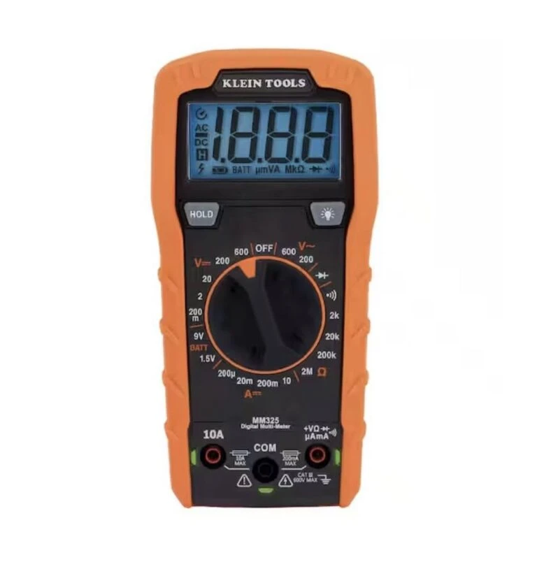
A digital multimeter (DMM)
If you don’t already have one, the Klein Tools MM325 is a reliable, beginner-friendly model with accurate resistance measurement and simple controls—perfect for testing potentiometers.
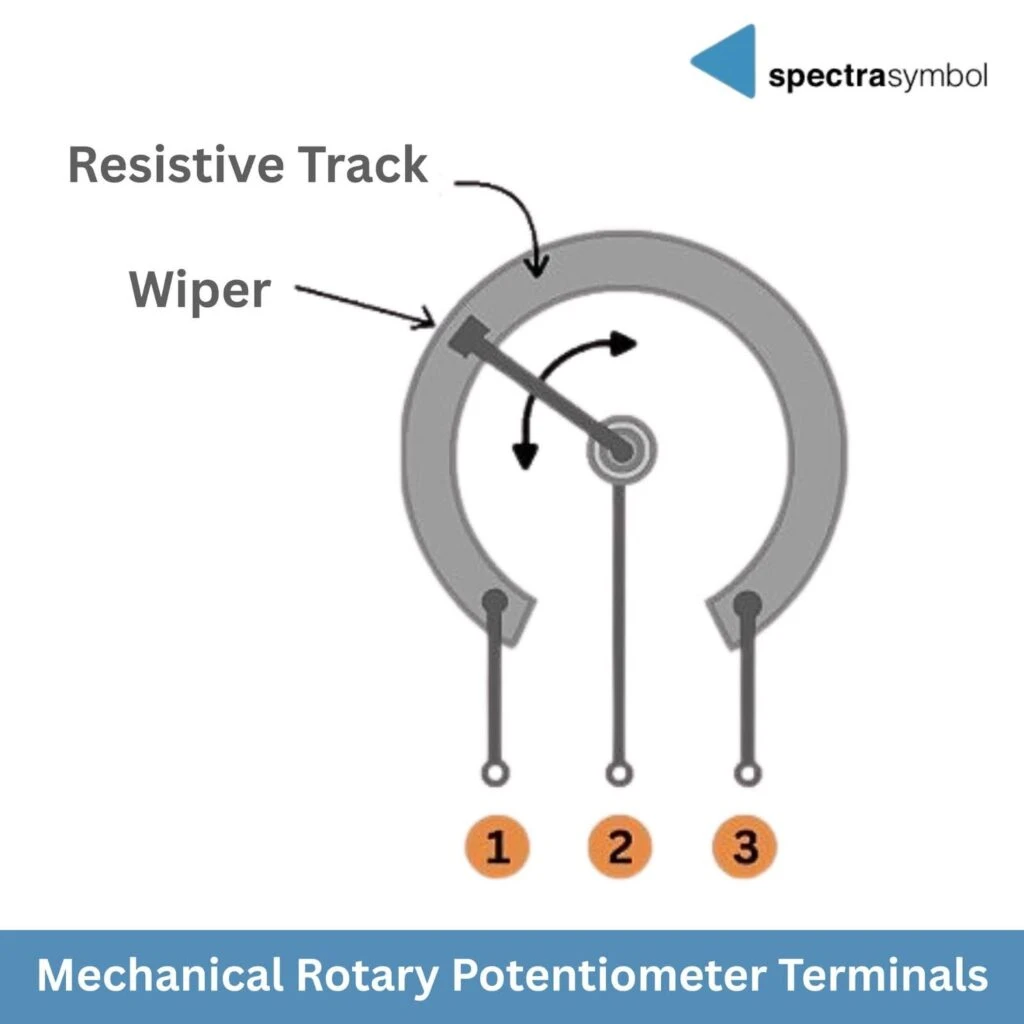
Understanding the Three Terminals
All potentiometers—mechanical, linear membrane, and rotary membrane—use the same three-terminal structure:
- Terminal 1: One end of the resistive track
- Terminal 2 (Wiper): The moving contact point
- Terminal 3: The other end of the track
Beginner tips:
- On most mechanical rotary potentiometers, the center terminal is the wiper.
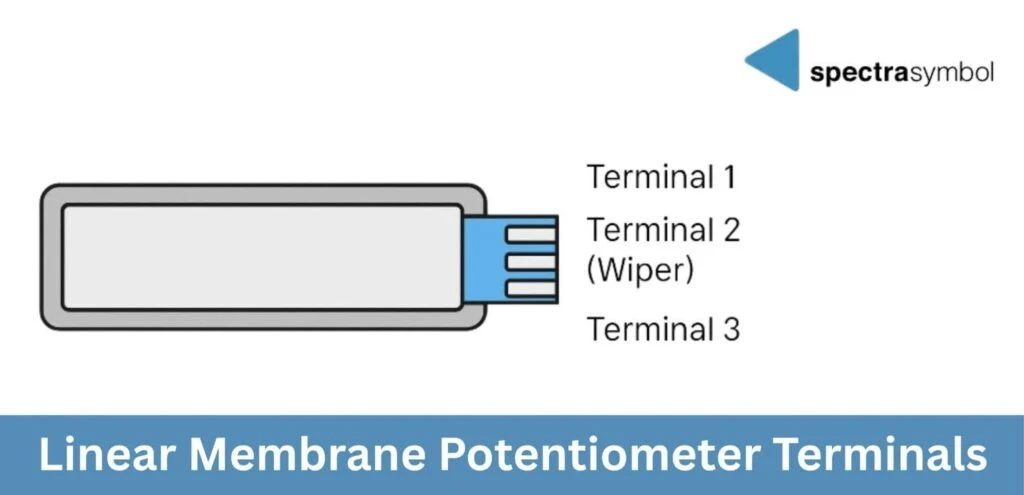
- On membrane potentiometers (linear and rotary), the wiper is usually the center pad on the tail connector.
Types of Potentiometers (Beginner Overview)
1. Mechanical Rotary Potentiometers
- Common in hobby electronics, guitar amps, knobs, and control panels
- Shaft rotates a wiper over a resistive track
2. Linear Membrane Potentiometers (SoftPot, ThinPot)
- Ultra-thin, flexible strips
- Three terminals on a flat tail
- Wiper is activated by pressing or sliding along the strip
3. Rotary Membrane Potentiometers (Spectra membrane rotary)
- Very thin circular form factor
- Operated by press + rotation or a low-profile actuator
- Same electrical behavior as a mechanical rotary pot
- The electrical testing method is identical: Terminal 2 always provides the position value relative to Terminal 1 or Terminal 3.

All three types test the same way—you just activate the wiper differently.
How to Test a Potentiometer With a Multimeter
Step 1: Test Total Resistance
This checks whether the resistive element is intact.
- Set your multimeter to Ω (resistance).
- Touch one probe to Terminal 1 and the other to Terminal 3.
- Compare the reading to the rated value printed on the part (e.g., 10 kΩ).
- A 10 kΩ pot should read close to 10 kΩ (±5%).
- Small fluctuations from probe movement are normal.
- Very high values → damaged or partially broken resistive track
- Very low values → short circuit or internal failure
- No reading → open circuit or broken terminal
Step 2: Test the Wiper Function
This verifies smooth, continuous movement across the resistive track.
Keep your meter in Ω mode.
A. Mechanical Rotary Pots
- Put one probe on Terminal 1 and the other on Terminal 2 (Wiper).
- Slowly rotate the knob.
- The resistance should change smoothly as you rotate—either increasing or decreasing depending on which end terminal you’re measuring against.
B. Linear Membrane Pots (SoftPot, ThinPot)
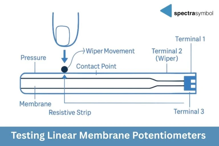
Linear membrane potentiometers activate when the top layer is pressed against the resistive strip.
You can test them in two ways:
- Press at different points to get discrete readings
- Press and slide lightly to check for smooth transitions
- Place one probe on Terminal 1, the other on Terminal 2 (Wiper).
- Press or slide along the strip.
- Resistance should change smoothly with finger position.
Repeat with Terminal 2 → Terminal 3.
C. Rotary Membrane Pots
Activation works the same way as linear membrane potentiometers but in a circular format:
- Press gently on the rotary surface to activate the wiper contact.
- Rotate the actuator or press-point while the probes measure Terminal 1 → Terminal 2.
- Watch for smoothly changing resistance as you rotate.
Step 3: Look for Noise, Jumps, or Dead Zones (Optional)
- Sudden drops to zero
- Random spikes
- Flat sections where the reading doesn’t change
- Wear on mechanical tracks
- Excessive force on the shaft or membrane
- Dust or contamination
- Cracks or damage in membrane layers
- Stress on solder joints
- Heat damage from soldering
Mechanical rotary potentiometers typically fail due to physical wear, while membrane potentiometers more often fail due to creasing, delamination, or damage to the tail.
Spectra Symbol’s thin-film membrane designs resist wear better than traditional carbon tracks, making them durable for repeated use.
When to Replace a Potentiometer
You should replace the pot if:
- Total resistance is far off from its rated value
- The wiper no longer changes resistance
- Dead zones are consistent
- Physical damage is visible (creases, torn tail, cracked casing)
Final Thoughts
Testing a potentiometer is fast, beginner-friendly, and helps you diagnose issues before spending hours troubleshooting wiring or code. Once you understand how the three terminals work and how the wiper behaves, testing becomes intuitive.
For builders who want thin, long-lasting, and reliable sensors, Spectra Symbol’s linear and rotary membrane potentiometers offer a flexible, durable alternative to mechanical pots.
Ready to upgrade your design with low-profile, long-lasting sensors? Explore Spectra Symbol’s full line of rotary and linear membrane potentiometers—and find the right fit for your next project.