
Analog Digital Ground Separation on Mixed-Signal PCBs: How to Preserve Clean Analog Signals
Author: David Marriott, Spectra Symbol CEO
Can I trust this reading by the time it reaches the ADC? That question surfaced again and again in conversations with engineers. Concerns about grounding, signal integrity, filtering, cable routing, and digital switching noise all pointed to the same underlying challenge: preserving a clean analog signal from the sensor to the microcontroller.
A linear potentiometer can produce an exceptionally stable analog voltage, yet still deliver noisy ADC readings if digital switching noise, poor grounding, or PCB layout compromises the signal before it reaches the converter.
This guide follows the analog signal from the potentiometer to the ADC, examining each stage where noise can be introduced, where analog digital ground separation helps (and where it’s often misunderstood), and the practical design decisions that lead to cleaner, more reliable measurements on mixed-signal PCBs.
See also: Linear Potentiometer Guide, How to Wire a Potentiometer, and Potentiometer Wiring & Pinout.
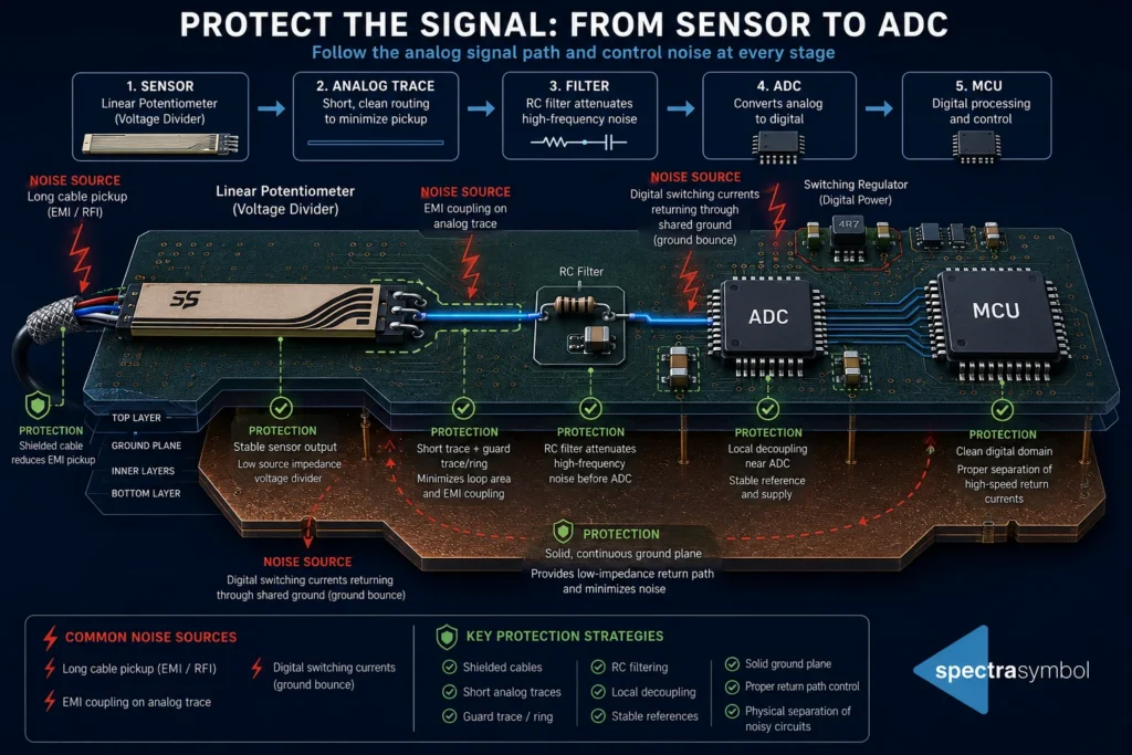
Why Mixed-Signal Boards Create Noise Problems
Analog signals are continuous and relatively low-energy. Digital circuits switch rapidly, creating fast return currents with every transition.
These return currents share copper unless intentionally managed. The resulting voltage differences along shared ground impedance appear at the ADC as noise superimposed on your sensor signal.
Key mechanisms include:
Ground impedance — Even small resistances and inductances in copper create voltage drops under current.
Return current paths — High-speed digital edges seek the lowest-impedance path back to the source.
Ground bounce and common impedance coupling — These turn digital activity into analog uncertainty.
The goal is not to eliminate every electron of digital noise, but to prevent it from corrupting the analog measurement path.
What Analog Digital Ground Separation Actually Means
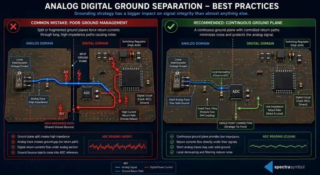
Many engineers were taught that analog and digital grounds should be completely split. In practice, modern recommendations from many MCU manufacturers favor a single, continuous ground plane with careful management of return currents.
Older split-ground advice came from an era of slower edges and higher impedances. Today, return-current control is usually more important than arbitrary plane splits.
Separate Noisy Current Paths — Not Necessarily Copper
Focus on directing high-current or high-speed digital return currents away from sensitive analog sections rather than cutting the ground plane.
When Separate Analog and Digital Ground Regions Make Sense
Separate regions (joined at a single point) can help in:
Isolated DC-DC converters
High-current motor drivers
Precision instrumentation
Mixed-voltage systems with significant potential differences
When a Single Uninterrupted Ground Plane Is Usually Better
A solid ground plane provides:
Lowest possible impedance
Predictable return paths
Fewer unexpected current loops
Analog Sensor Noise: Following the Signal from Sensor to ADC
Even with excellent grounding, the analog signal can pick up noise at multiple stages.
At the Sensor
Noise sources include EMI, cable pickup, mechanical vibration, contact variation, and high source impedance.
Along PCB Traces
Long analog traces become antennas. Problems increase when traces run parallel to clocks, switching regulators, or motor drivers.
Mitigation techniques: shielding, generous spacing, and strategic guard traces.
At the ADC Input
Sampling capacitors, source impedance, and acquisition time all matter. Consider buffering, simple RC filters, and anti-aliasing where needed.
Key Principle: Clean analog measurements are usually the result of dozens of small layout decisions rather than one magic filtering technique.
Reading a Linear Potentiometer Reliably
A linear potentiometer is electrically straightforward — it operates as a voltage divider with stable resistance and predictable output. Yet repeatable measurements depend heavily on the surrounding system design.
Power Supply Quality
Use a clean, well-regulated supply with proper decoupling.
Ground Reference Consistency
Tie directly back to careful return-current management and a low-impedance ground.
ADC Reference Voltage
A stable reference voltage is essential for accurate conversion.
PCB Layout Considerations
Keep analog traces short
Avoid routing near switching nodes
Place decoupling capacitors close to the device
Keep high-current return paths away from analog sections
Signal Path Overview:
Linear Potentiometer
↓ (Voltage Divider Output)
Analog Trace (short, protected)
↓
Optional RC Filter / Buffer
↓
ADC Input
↓
MCU Digital Domain
Protect the signal at every step rather than hoping to fix it later in software.
Related resources: Linear Potentiometer Overview, MagnetoPot Contactless Sensors, and Thin and Flexible Potentiometers.
Potentiometer Wear and Signal Stability
From a signal perspective, wear in a potentiometer often appears as:
- Contact resistance variation
- Intermittent noise or small discontinuities
- Increased sensitivity to vibration
- Effects from environmental contamination
Many engineers first suspect grounding or layout issues when readings become unstable. In reality, the cause can be mechanical (worn contact), wiring, connector oxidation, or an unstable reference voltage — all producing similar symptoms. Distinguishing the root cause is key to an effective fix.
Practical Grounding Checklist for Mixed-Signal PCB Design
| Goal | Recommended Practice |
|---|---|
| Reduce ADC noise | Keep analog traces short |
| Reduce switching interference | Keep digital return currents away from analog inputs |
| Lower ground impedance | Use continuous ground planes when practical |
| Prevent reference instability | Decouple analog supplies thoroughly |
| Improve repeatability | Filter before the ADC when appropriate |
| Reduce cable noise | Shield long sensor cables |
| Improve measurements | Use stable voltage references |
Common Grounding Mistakes
Splitting the ground plane unnecessarily
Routing analog traces over ground gaps or slots
Sharing analog returns with motor or high-current paths
Ignoring ADC input impedance and acquisition requirements
Assuming software filtering can fully compensate for hardware problems
Firmware can reduce noise, but it cannot recover information that never reached the ADC cleanly.
Frequently Asked Questions
Should analog and digital grounds always be separated?
Not always. A single well-managed ground plane is often superior. Use partitioned grounds only when specific isolation needs justify it.
What causes analog sensor noise?
Return current coupling, EMI pickup, long traces, poor decoupling, and mechanical issues at the sensor.
Why is my potentiometer reading unstable?
Common culprits: ground noise, unstable references, mechanical wear, poor connections, or inadequate filtering.
Does shielding help analog sensors?
Yes, especially for long cables or high-EMI environments.
Should I filter my potentiometer before the ADC?
A simple RC filter is often beneficial for anti-aliasing and noise reduction, provided it doesn’t violate the ADC’s source impedance requirements.
Conclusion
Engineers often focus first on the sensor specification, but real-world performance depends on protecting the signal through the entire system. Careful grounding, thoughtful PCB layout, and proper signal conditioning ensure the ADC measures the sensor — not the electrical environment around it.
Protect the signal. Don’t just read it.
For more resources, explore our Engineering Resource Center and Sensor Selection Guide, including guides on Different Types of Position Sensors.