
How to Wire a Potentiometer: Step-by-Step Diagrams for Any Application
Author: David Marriott, Spectra Symbol CEO
Potentiometers typically have three terminals, with the center pin serving as the wiper. Wiring depends on your specific application, but most uses fall into one of two categories: voltage divider mode (most common) or rheostat mode.
This guide provides clear, step-by-step diagrams and instructions for common scenarios. Whether you’re working on an Arduino project, audio volume control, or motor speed adjustment, you’ll find exactly what you need.
If you’d like a deeper explanation of potentiometer construction, terminal naming conventions, and electrical theory, see our Potentiometer Wiring & Pinout Guide.
The Quick Answer: Standard 3-Pin Potentiometer Wiring
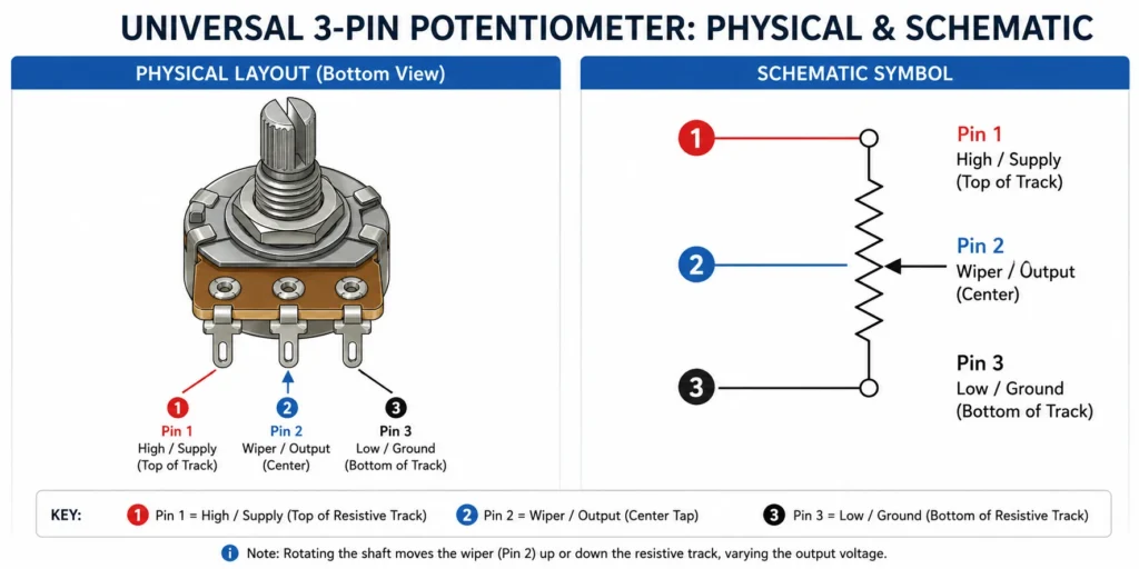
Golden Rule:
- Pin 1: One end of the resistive track (Power input, reference voltage, or signal in)
- Pin 2: Wiper (Variable output)
- Pin 3: Other end of the resistive track (Ground or return path)
Important: Swapping the two outer terminals (Pin 1 and Pin 3) will typically not damage the circuit as long as the recommended power rating is not exceeded — it simply reverses the direction of adjustment (e.g. clockwise vs counterclockwise).
How to Identify Potentiometer Pins
Method 1: Use the Datasheet
Most manufacturers label terminals as 1-2-3, where Terminal 2 is the wiper—though for membrane potentiometers, Spectra Symbol designates this as the “collector.”
Terminal layouts vary significantly by technology and manufacturer. For example, a MagnetoPot (MP1) uses a completely different pinout configuration than standard rotary or SoftPot models. Miswiring these specific pins can cause an immediate short circuit and burn out the sensor. As a best practice, you should always map your leads according to the specific engineering datasheet of the product you are using rather than relying on a standard 1-2-3 layout.
Method 2: The Multimeter Test
Set your multimeter to resistance (ohms) mode.
Probe any two terminals and slowly adjust the wiper position (e.g. turn the shaft).
If resistance stays constant → you’ve found the two resistor terminals.
Probe the remaining terminal against one outer terminal while turning the shaft.
If resistance changes smoothly → that is the wiper pin .
The Two Fundamental Wiring Modes
| Feature | Voltage Divider (3-Pin) | Rheostat (2-Pin) |
|---|---|---|
| Pins Used | All 3 | 2 (Wiper + one resistor) |
| Output | Variable Voltage | Variable Resistance |
| Most Common Use | Adjust voltage in low-power signals (e.g. Arduino based position sensor) | Control the flow of electrical current (e.g. DC motor control) |
| Frequency | Most common | Less common |
Voltage Divider Wiring (3-Pin Setup)
This is the most popular configuration. It produces a variable output voltage proportional to the wiper position.
A three-terminal potentiometer acts as a voltage divider. As the wiper moves, it changes the ratio between the two internal resistances, producing a proportional output voltage. The diagram below shows the operation at three representative positions.
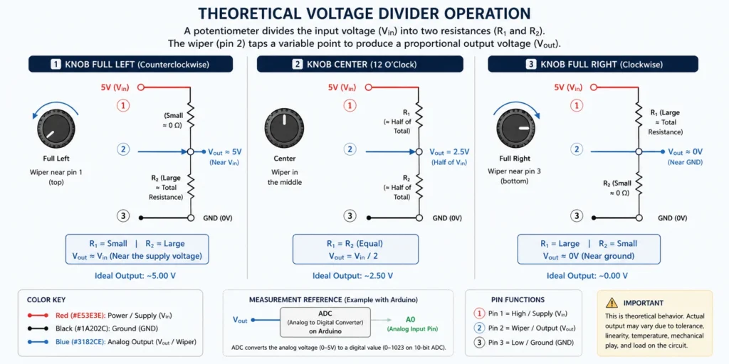
The resistive element is effectively divided into two sections: R₁, the resistance between the supply voltage and the wiper, and R₂, the resistance between the wiper and ground. The output voltage is determined by the ratio between these two resistances:
> V_{out}=V_{in}\times\frac{R_2}{R_1+R_2} >
Because the total resistance (R_1 + R_2) remains essentially constant, moving the wiper simply changes the ratio between the two sections, producing a proportional change in output voltage. This variable voltage is exactly what analog inputs on microcontrollers such as an Arduino measure using an analog-to-digital converter (ADC).
Best for:
- Arduino projects
- PLC analog inputs
- Sensor calibration
- Position sensing
SoftPot potentiometers use the same voltage divider principle — only the physical form factor changes (flat and flexible instead of rotary). See our guides on Thin and Flexible Potentiometers and the SoftPot Product Page.
Rheostat Wiring (2-Pin Setup)
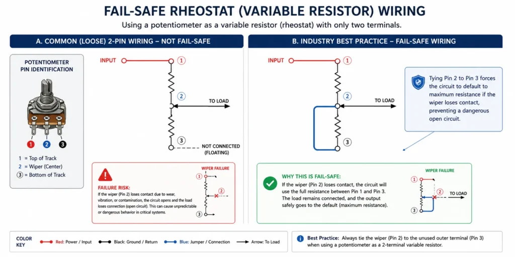
In some applications, a potentiometer can be used as a rheostat by using 1 resistor pin and the wiper pin:
It is important to note that standard potentiometers, including membrane potentiometers like Spectra Symbol’s line of membrane potentiometers are built with thin resistive tracks (like carbon film) meant for low-power signals (typically a fraction of a watt). If you try to use a standard potentiometer to control the speed of a large DC motor, the high current can literally burn the track and destroy the component.
Engineering Best Practice: When using a potentiometer as a rheostat, tie the unused resistor terminal (e.g. Pin 3) to the wiper (e.g. Pin 2). This provides a fail-safe: if the wiper loses contact, the circuit defaults to maximum resistance instead of an open circuit, however, doing so doesn’t increase its power rating. It will still burn out if you put too much current through it!
Can You Reverse the Polarity of the Resistor Pins?
Yes — and, as long as you are operating within the specified power range, the potentiometer will still function. However, reversing the resistor’s terminals changes whether the wiper movement increases or decreases the output on the wiper pin and the circuit design will have to compensate for that change.
Application-Specific Wiring Guides
How to Wire a Potentiometer to an Arduino
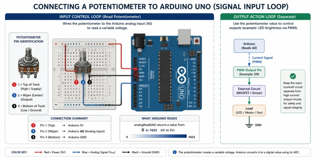
Arduino 5V ───── Pin 1
Arduino A0 ───── Pin 2 (Wiper)
Arduino GND ──── Pin 3
Important: The potentiometer does not directly control devices like LEDs or motors. The Arduino reads the voltage on the analog pin, processes it in code, and then controls the output.
C++
void loop() {
int sensorValue = analogRead(A0); // Returns 0-1023
// Use sensorValue for LED brightness, servo angle, etc.
}
See our full tutorial: How to Use a Potentiometer with Arduino.
How to Wire a Potentiometer for Volume Control
Audio In |
Key Concept: The potentiometer acts as a variable signal attenuator.
Audio Note: Use logarithmic (audio) taper potentiometers for natural volume response. Linear taper pots often feel unnatural because human hearing is logarithmic.
How to Wire a Potentiometer to a Motor
Critical Warning: Never wire a standard potentiometer directly in series with a motor. Most pots are rated 0.1W–1W, while motors draw far more current. This will overheat and destroy the potentiometer.
Correct Method:
Use the potentiometer to control a motor driver or PWM controller:
Pot (Voltage Divider) → Motor Controller / PWM Input → Motor
Common in conveyor systems, fans, actuators, and industrial process equipment.
Common Potentiometer Wiring Mistakes
| Problem | Cause | Solution |
|---|---|---|
| Knob works backwards | Outer terminals reversed | Swap Resistor Pins |
| No output change | Wiper not connected correctly | Verify the wiper pin is connected |
| Pot gets hot | Driving load directly / Input power too high | Use a motor controller / Verify power supply is correctly sized |
| Signal jumps / noisy | Worn track or poor connection | Verify secure connections to the terminals and clean or replace the potentiometer |
| Erratic behavior | Wrong mode (divider vs rheostat) | Double-check wiring configuration |
Selecting the Best Potentiometer for Your Environment
- Rotary Potentiometers: Ideal for knobs, instrument panels, and audio controls.
- Linear (Slide) Potentiometers: Best for sliders and direct position feedback.
- Thin and Flexible Potentiometers: Perfect for space-constrained designs, custom HMIs, medical devices, and low-profile interfaces.
Explore more in Different Types of Position Sensors and Thin and Flexible Potentiometers.
Conclusion
Every potentiometer wiring configuration ultimately falls into one of two categories: voltage divider or rheostat. Once you understand these two methods, you can confidently wire potentiometers for Arduino projects, audio systems, motor controllers, industrial equipment, and position sensing applications.
Proper wiring, correct pin identification, and respect for power limits will keep your projects reliable and safe.
For product options and custom solutions, visit the Spectra Symbol Potentiometer Collection.
Recommended Next Reads: